ESP32 Fundamental Structure Arduino and MicroPython Sketch
In this section, you’ll learn about the fundamental structure of an Arduino sketch and MicroPython script, which is essential for programming the ESP32.
What We Will Learn in This Section
- Understanding the components of an Arduino and MicroPython sketch.
- Familiarising with the setup() and loop() functions.
- Implementing basic LED control using an Arduino sketch and MicroPython script.
Why Is This Lesson Important to You?
Understanding the structure of an Arduino sketch is crucial as it forms the basis for programming your ESP32 board effectively. This knowledge allows you to create and execute code to control various peripherals and sensors connected to your ESP32.
Components List:
These components are essential for setting up and running the basic LED control project outlined in the section. Adjustments may be needed based on specific board variations or project requirements.
Arduino and MicroPython for ESP32"
is your go-to guide for mastering ESP32 projects with clear examples and practical code. For free reading, visit Mechatronics Lab and grab your copy here
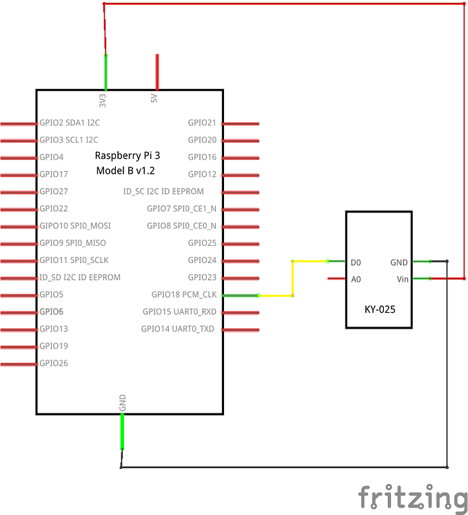
Circuit Diagram
- LED Anode (long leg): Connect this leg to ESP32 pin GPIO 13 using a resistor.
- LED Cathode (short leg): Connect this leg to the GND pin on the ESP32.
- USB Cable: Plug one end into the ESP32 and the other end into your computer to provide power and allow programming.
Connect ESP32 to the computer via USB for programming and power.
Arduino Code
// Define the GPIO pin connected to the LED
const int LED_PIN = 13; // Use GPIO 13 for onboard LED on most ESP32 boards
void setup()
{
pinMode(LED_PIN, OUTPUT); // Initialize the LED pin as an output
}
void loop()
{
digitalWrite(LED_PIN, HIGH); // Turn the LED on (HIGH level)
delay(1000); // Wait for 1 second
digitalWrite(LED_PIN, LOW); // Turn the LED off (LOW level)
delay(1000); // Wait for 1 second
}
Here’s an explanation of the code:
1. Defining the GPIO Pin
const int LED_PIN = 13;: This line defines a constant integer LED_PIN and assigns it the value 13. This value represents the GPIO pin number connected to the LED. In this case, GPIO 13 is typically used for the onboard LED on many ESP32 boards.
2. Setup Function
void setup(): This is the setup function that runs once when the ESP32 is powered on or reset.
pinMode(LED_PIN, OUTPUT);: This line configures GPIO 13 as an output pin. This means the pin can now send a voltage signal to control the LED.
3. Loop Function
void loop(): This function runs repeatedly, allowing the code inside it to be executed in a continuous loop.
digitalWrite(LED_PIN, HIGH);: This command sends a HIGH signal to the LED pin, turning the LED on by applying a voltage.
delay(1000);: The program waits for 1000 milliseconds (1 second) before executing the next instruction.
digitalWrite(LED_PIN, LOW);: This command sends a LOW signal to the LED pin, turning the LED off by removing the voltage.
delay(1000);: Again, the program waits for 1 second before repeating the loop.
MicroPython Code
from machine import Pin
import time
# Define the GPIO pin connected to the LED
LED_PIN = 13 # Use GPIO 13 for onboard LED on most ESP32 boards
# Initialize the LED pin
led = Pin(LED_PIN, Pin.OUT)
# Loop to blink the LED
while True:
led.on() # Turn the LED on
time.sleep(1) # Wait for 1 second
led.off() # Turn the LED off
time.sleep(1) # Wait for 1 second
Here’s an explanation of the code:
1. Importing Modules
from machine import Pin: Imports the Pin class from the machine module, which allows you to control GPIO pins on the ESP32.
import time: Imports the time module, which provides functions to work with time, such as delays.
2. Defining the GPIO Pin
LED_PIN = 13: Defines the GPIO pin number for the LED. GPIO 13 is typically used for the onboard LED on many ESP32 boards.
3. Initializing the LED Pin
led = Pin(LED_PIN, Pin.OUT): Initializes the LED pin as an output pin by creating a Pin object. The Pin.OUT parameter specifies that the pin will be used for output, allowing it to control the LED.
4. Main Loop
while True:: Starts an infinite loop, which will run continuously until the program is stopped.
led.on(): Turns the LED on by sending a HIGH signal to GPIO 13.
time.sleep(1): Pauses the program for 1 second.
led.off(): Turns the LED off by sending a LOW signal to GPIO 13.
time.sleep(1): Pauses the program for 1 second before repeating the loop.
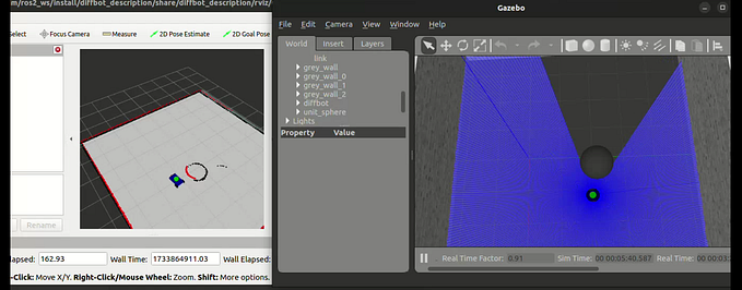
Output
Summary
Understanding and implementing basic LED control with both Arduino and MicroPython on an ESP32 board lays a solid foundation for more advanced projects. Here are key takeaways:
Arduino vs. MicroPython: Arduino offers a familiar C/C++-like environment, ideal for beginners and those comfortable with structured programming. MicroPython, on the other hand, provides a Pythonic interface, facilitating rapid prototyping and ease of use.
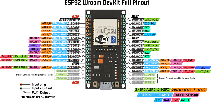
Hardware Setup: Ensure your ESP32 board is correctly connected and powered via USB. Double-check pin configurations to match your board’s layout and specifications.
Programming Concepts: Concepts such as pin initialization (pinMode in Arduino, Pin class in MicroPython), digital output (digitalWrite in Arduino, on() and off() methods in MicroPython), and timing (using delay() in Arduino, time.sleep() in MicroPython) are fundamental to controlling peripherals like LEDs.
Further Exploration: Experiment with different GPIO pins, modify blinking patterns, or integrate additional sensors and actuators to expand your project’s functionality
Originally published at https://www.hackster.io.